The palatial country residence of Capt. J. R. DeLamar. at Glen Cove, L. I., to cost $275,000, now being designed by C. P. H. Gilbert, architect, New York City, is to be heated and ventilated by the Harrison Aertube heater system to be installed by the Harrison Engineering Co., New York City, which has the contract for the entire plant. ***Domestic Engineering - 1910***

The photograph shows the new residence at Glen Cove, L. I., of Captain J. M. DeLamar, now under construction. The building is 150 feet long, 100 feet wide and three stories in height, and is fire-proof throughout, the floors being of steel and terra cotta.
The structure contains approximately 250 tons of structural steel, an exceptionally large tonnage for this class of construction. All of the structural steel and ornamental iron was painted with two coats of Dixon's Silica-Graphite. The steel contractor for this work was Fitzpatrick & Coombs, of New York City. ***Graphite - 1909***
The Isolated Sewage Disposal System
A Type Adaptable to the Country Residence
By WILLIAM C. TUCKER
 |
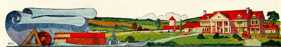
| COUNTRY ESTATE OF THE LATE CAPTAIN DE LAMAR AT GLEN COVE, LONG ISLAND, N. Y. C. P. H. GILBERT, ARCHITECT |
evolving a plan both simple in construction and effcient in operation.
Former methods of draining household waste material either into a cesspool or a nearby stream are no longer countenanced and these methods cannot be too strongly condemned, nor their attendant dangers overemphasized.
The underlying principles to produce complete bacterial reaction are quiescence, sedimentation and the delivery of the material for treatment in as dense a form as is expedient, with sufficient fluid only to hold the solids in suspension so that they may be moved in the sewer with celerity and freedom. To produce these results the sewage must be delivered to a water-tight masonry chamber of sufficient capacity to retain the accumulation of two days' supply. The receiving basin must be so constructed that the movement of the sewage during its passage to final disposal may be leisurely.
 |
| ESTATE OF THE LATE CAPTAIN DELMAR AT GLEN COVE, LONG ISLAND N. Y. THE SEWAGE DISPOSAL SYSTEM SHOWN HERE HAS BEEN IN SATISFACTORY OPERATION FOR SEVERAL YEARS |
The receiving basin must be of the correct size. This cannot be determined until the daily water consumption within the house is known. The depth of sewage should, if possible, not be over 4 ft. 6 in., which has been generally accepted as correct from numerous scientific experiments. The receiving basin may be circular in form for smaller units, including those of 600 gallons capacity ; if larger, the rectangular form will be found more advantageous. The determination of the water consumption within the house is somewhat difficult and is dependent upon its availability, whether there be running water or not. In the former instance, 60 gallons per head per day may be assumed as a fair allowance. No animal stall or wash table drainage should enter the sewage disposal system, since that from the former contains finely masticated food of the animals, which fails to settle in the receiving basin, causing clogging and serious interference with the proper action of the filtering media. The road material carried by the drainage from wash tables quickly settles in the sewers, causing interruption of flow and final stoppage.
The location and character of the surrounding material, for final disposition, for whatever mode may be employed, is most important and cannot be selected with indifference. The location should be upon gradual, sloping, unshaded ground exposed to the sun arid at considerable distance from growing shrubbery or trees whose root tendrils may seek the nitrogen in the effluent, enter the sewer pipe and interfere with the free absorption by the earth. The surrounding material must be of gravel or sand ; loam and hardpan should be avoided as much as possible on account of their non-absorbent qualities.
When this is impracticable the means of disposal must be considerably increased or the unit subdivided. An area of generous proportions is necessary for final disposal, situated at some rather remote and protected point and should not be used for general farming purposes, nor traversed by the farm implements. It should be placed at as great a distance from the source of the water supply as is practical to avoid contamination.
The scientific method of sewage disposal is most elementary and mechanical in its application, and consists of consigning the effluent to the earth in such quantities and manner that it may be readily and continuously absorbed. This may be accomplished in a number of ways which differ radically from each other in form and cost, but the underlying principle is the same.
 |
| FIG. 1. THE TYPE OF ISOLATED SEWAGE DISPOSAL SYSTEM ABOVE ILLUSTRATED FOLLOWS THE MOST ADVANCED METHODS YET DEVELOPED |
discharged into disposal fields, primary and secondary, one of which is always in use, generally for a period of two weeks, while the other is at rest, recuperating, as demanded by good practice. The valve shown on the siphon discharge directs the flow to either field as desired. These disposal fields consist of lateral lines of drainage tile laid a short distance below the surface of the ground.
The laterals, a cross section of which is shown in Fig. 1, consist of 3-inch tile laid with open joints, protected against falling material by caps, laid 10 to 12 inches below the surface of the ground and surrounded on top and sides with a 4-inch layer of 1-inch broken stone or furnace slag which is protected by a thick layer of salt hay against the filling entering the interstices. These lines are taken from 4-inch sanitary right and left Y's with 3-inch branches, are spaced 3 to 4 feet apart, as shown in Fig. 1, are laid very flat, with a fall of but 6 inches in their entire length, and are approximately 80 feet long. This length has been scientifically determined as correct, so that each siphon discharge completely fills all lines, allowing the contents slowly, to seep into the surrounding media through the open joints.
 |
| FIG. 2. THE STEPPED UP ARRANGEMENT OF THE MAIN FEEDERS HERE SHOWN IS NECESSARY WHEN THESE ARE LAID ON STEEPLY SLOPING GROUND |
It often develops that a hillside is the only available space upon which to locate the disposal field, which necessitates special forms for the main feeders, so that the onrush at each siphon discharge may not burst through to the surface at the end, and not completely fill each lateral. To obviate this and reduce the velocity of flow to a normal rate, the main feeders are installed in a series of steps, as shown in Fig. 2, with the horizontal space between each step laid flat, so that the rate of flow is greatly reduced.
The country estate of the late Captain De Lamar at Glen Cove, L. L, is here shown and the sewage disposal system installed is clearly indicated. ***The American Architect - 1920***
For more on "Pembroke" visit oldlongisland.com and Mansions of the Gilded Age.
Great find!
ReplyDeleteA little late to comment but yes, the photo under construction is amazing as is the aerial view of Pembroke. What a showplace. NYarch
ReplyDelete